Home > Valve > Automatic Control Valve
Float Control Valves
Features
This valve maintains constant liquid level in a tank. The pilot is sensitive to slight changes in level. The main valve open when level drops and closes when level rises. The valve consists of basic valve and buoyancy pilot and controls the outflow in a water tank supply. It is installed on the inlet of a water pool or tower. 100X Float Control Valves is controlled by the floating pilot valves to close the inlet to stop water supply when the water level gets to the preset height and to open the inlet to supply water to the water tower or pool when the water level is lower than the preset one, so as to realize the automatic water control according to the changing water level. It features by the high accuracy of level control, water pressure disturbance resisting, mountable on any positions, reliable seal performance, easy installation, maintenance, debugging and check, long duration (The floating pilot valve can be separately mounted from the main one).
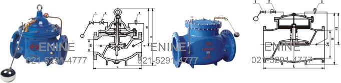
Float Control Valves
DN 450 Diaphragm type valve
DN 500 piston type valve
Notes:
1. Float Ball Pilot Valve
2. Ball Valve
3. Needle Valve
Technical Parameters
Nominal Pressure: 1.0, 1.6, 2.5MPa
Shell test pressure: 1.5, 2.4, 3.75MPa
Sealed test pressure : 1.1, 1.76, 2.75MPa
Suitable temperature: 80
Suitable medium: water, Sewage
Materials
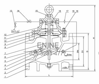
| Serial No. | Part | Material |
| 1 | Body | Cast Iron (GG25, HT200) / Ductile Iron (GG40, QT) |
| 2 | Seat | 2Cr13 / SS 304 / SS 316 |
| 3 | Stem | 2Cr13 / SS 304 / SS 316 |
| 4 | O-ring Gasket | Cast iron |
| 5 | O-ring | NBR |
| 6 | O-ring | NBR |
| 7 | Disc | Cast Iron (GG25, HT200) / Ductile Iron (GG40, QT) |
| 8 | Diaphragm | Rubber |
| 9 | Diaphragm washer | Ductile Iron |
| 10 | Nut | Bronze |
| 11 | Spring | Spring steel |
| 12 | Cover | Cast Iron (GG25, HT200) / Ductile Iron (GG40, QT) |
| 13 | Pilot valve | Bronze |
| 14 | Ball valve | Bronze |
| 15 | Hang ring | Steel |
| 16 | Pilot socket | Bronze |
| 17 | Needle valve | Bronze |
| 18 | Screw | Steel |
| 19 | Stud | Steel |
Dimensions
| DNmm | 20 | 25 | 32 | 40 | 50 | 65 | 80 | 100 | 125 | 150 | 200 | 250 | 300 | 350 | 400 | 450 | 500 | 600 | 700 | 800 | |
| L | 180 | 180 | 180 | 203 | 203 | 235 | 285 | 360 | 400 | 455 | 585 | 650 | 800 | 860 | 915 | 980 | 1075 | 1230 | 1300 | 1450 | |
| PN10 | D | 105 | 115 | 135 | 145 | 160 | 180 | 195 | 215 | 245 | 280 | 335 | 390 | 440 | 500 | 565 | 615 | 670 | 780 | 895 | 1010 |
| D1 | 75 | 85 | 100 | 110 | 125 | 145 | 160 | 180 | 210 | 240 | 295 | 350 | 400 | 460 | 515 | 565 | 620 | 725 | 840 | 950 | |
| PN16 | D | 105 | 115 | 135 | 145 | 160 | 180 | 195 | 215 | 245 | 280 | 335 | 405 | 460 | 520 | 580 | 640 | 705 | 840 | 910 | 1020 |
| D1 | 75 | 85 | 100 | 110 | 125 | 145 | 160 | 180 | 210 | 240 | 295 | 355 | 410 | 470 | 525 | 585 | 650 | 770 | 840 | 950 | |
| PN25 | D | 105 | 110 | 135 | 145 | 160 | 180 | 195 | 230 | 270 | 300 | 360 | 425 | 485 | 550 | 610 | 660 | 730 | 840 | 955 | 1070 |
| D1 | 75 | 85 | 100 | 110 | 125 | 145 | 160 | 190 | 220 | 250 | 310 | 370 | 430 | 490 | 550 | 600 | 660 | 770 | 875 | 990 | |
| H | 212 | 212 | 212 | 265 | 265 | 310 | 350 | 460 | 520 | 570 | 695 | 780 | 905 | 1025 | 1080 | 1030 | 1135 | 1270 | 1460 | 1640 | |
| H1 | 179 | 179 | 179 | 210 | 210 | 215 | 245 | 305 | 365 | 415 | 510 | 560 | 658 | 696 | 735 | 610 | 665 | 725 | 865 | 975 | |
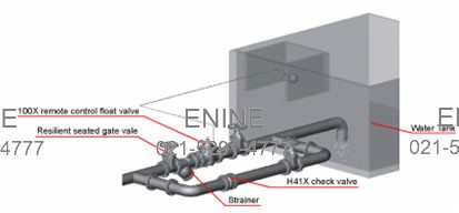
Typical Installation

- Ball Valves
- Butterfly Valves
- Cast Steel Valves
- Bellows Seal Valves
- Forged Steel Valves
- Regulate Valves
- Balance Valves
- Check Valves
- Safety Valves
- Instrumentation Ball Valves
- Resilient Seated Gate Valves
- Safety Relief Valves
- Plug Valves
- Globe Valves
- Discharge valves
- Instrument Manifolds
- Needle & Gauge Valves
- Automatic Control Valves
