Home > Pump > Multi Stage Pumps
Vertical Multistage Centrifugal Pump
I Product characteristics for Vertical Multistage Centrifugal Pump
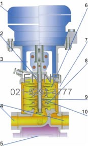
Structure Of Vertical Multistage Centrifugal Pump
- Low noise: Install the model number of Y2 electric motor,the circulate is steady,and low noise
- Without leakage: Specially selected mechanical seal and science processes a craft,professional technical assurance,carry out the pursue of"without leakage"
- Simple to demolish and install: Rigid couplings,spline shaft design,the weight ease 50% than the pumps,and the operability is better
- Install is convenient: Enter of water and out of water are on the same level,the Lower to the tube road request,the the and tube road the s usage is more dependable,the stability is higher
- The investment of pump - house - building is less: At the orginally foundation of vertical
- multistage pump go forward to go an improvement,the the physical volume is small,covering area little
- Avoid the second-pollution of the fluid matter: Inducer and shaft are made of stainless steel,overcome the weakness of the cast-iron pump,promise the quality of the fluid matter
- Have no rust eclipse harassment: The use cylinder of stainless steel,better adapt various environment,never rusty
- The life span is longer: The material hurtles of stainless steel are pressed,the weld impeller,the weight is light,balance good,circulate a stability
- Support expenses low: The Adopt the water-lubrication-bearing design,Circulate more dependable,need not to lubriicate to maintain
- Efficiently and economize on energy: The More excellent water power model,the smooth of over flow a parts,raised a machine efficiency consumedly
II Performance scope for Vertical Multistage Centrifugal Pump
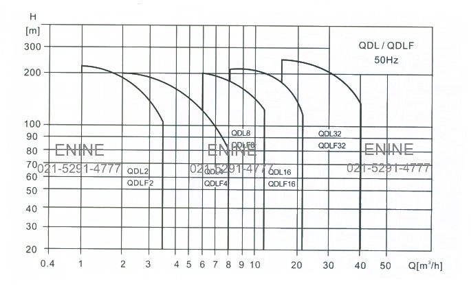
II Performance scope for Vertical Multistage Centrifugal Pump
III Product range for Vertical Multistage Centrifugal Pump
Description |
QDL2 | QDL4 | QDL8 | QDL16 | QDL32 |
| Rated flow [m3/h] | 2 | 4 | 8 | 16 | 32 |
| Rated flow [1/s] | 0.56 | 1.1 | 2.2 | 4.4 | 8.9 |
| Flow range [m3/h] | 1~3.5 | 1.5~8 | 5~12 | 8~22 | 16~40 |
| Flow range [1/s] | 0.28~0.97 | 0.42~2.2 | 1.4~3.3 | 2.2~6.1 | 4.4~11.1 |
| Max.pressure [bar] | 23 | 21 | 21 | 22 | 26 |
| Motor power [kw] | 0.37~3 | 0.37~4 | 0.75~7.5 | 2.2~15 | 1.5~30 |
| Temperature range [ ] | -15~+120 | ||||
| Max.efficency | 46 | 59 | 64 | 70 | 76 |
| Type | |||||
| QDL | |||||
| QDLF | |||||
| QDL pipe connection | |||||
| DIN Flange | DN25 | DN32 | DN40 | DN50 | DN65 |
| Pipe thread | |||||
IV Application scope for Vertical Multistage Centrifugal Pump
QDL/QDLF is a king of multifunctional products. It can be used to convey various medium from tap water to industrial liquid at different temperature and with different flow rate and pressure. QDL type is applicable to conveying-corrosive liquid,QDLF is suiable for slightly Corrosive liquid.
Water supply:Water filter and transport in water works, boosting of main pipeline, boosting in high-rise buildings.
Industrial boosting:Process fiow water system, cleaning system, High-pressure washing system, fire fighting system.
Industria liquid conveying: Cooling and air-conditiong system, Boiler water supply and condensing system, machine-associated purpose, acids and alkali.
Water treatment:Ulrafitation system, reverse osmosis system, Distillation system, separator, swimming pool
Irrigation:Farmland irrigation, spray irrigation, dripping irrigation.
V Operation conditions for Vertical Multistage Centrifugal Pump
Medium :Thin,clean,noon-flammable and non-explosive liquid containing No solid granules and fibers.
Liquid temperature type:-15
~+70
Hot water type:+70
~+120
Ambient temperature:up to +40
Altitude:up to 1000m
VI Vertical Multistage Centrifugal Pump
QDL/QDLF is a kind of vertica non-self priming multistage .Centrifugal pump, which is driven by a standard electric motor. The motor output shaft directly connects with the pump Shaft through a coupling. The pressure-resistant cylinder and flow passage components are fixed between pump head and in-located at the pump bottom at the same plane. This kind of pump can be equipped with an intelligent protector to effectively prevent it from dry-running, out-of-phase and overload
VII Electric motor for Vertical Multistage Centrifugal Pump
Full-enclose air-blast two-pole standard motor. Protection class:IP55;Insulation class:F
Standard voltage:50Hz:1
20-230/240V;3
00-220/346-380V;3
20-240/380-415V;3
80-415V
VII Electric motor for Vertical Multistage Centrifugal Pump
The maximum inlet pressure is the table below. But the actual inlet pressure plus the valve close pressure allowable working pressure
Model |
Max inlet pressure |
| QDL, QDLF2 | |
| QDL,QDLF2-20 | 6[bar] |
| QDL,QDLF2-30~2-110 | 10[bar] |
| QDL,QDLF-130~2-260 | 15[bar] |
| QDL,QDLF4 | |
| QDL,QDLF4-20 | 6[bar] |
| QDL,QDLF4-30~4-100 | 10[bar] |
| QDL,QDLF4-120~4-220 | 15[bar] |
| QDL,QDLF8 | |
| QDL,QDLF8-20/1~8-60 | 6[bar] |
| QDL,QDLF8-80~8-200 | 10[bar] |
| QDL,QDLF16 | |
| QDL,QDLF16-20~16-30 | 6[bar] |
| QDL,QDLF16-40~16-160 | 10[bar] |
| QDL,QDLF32 | |
| QDL,QDLF32-10-1~32-20-2 | 3[bar] |
| QDL,QDLF32-20~32-40 | 4[bar] |
| QDL,QDLF32-50-2~32-100 | 10[bar] |
| QDL,QDLF32-110-2~32-140 | 15[bar] |
IX Max Working Pressure
Model |
Curve number |
| QDL,QDLF2 | |
| QDL,QDLF2-20~150 | 1 |
| QDL,QDLF2-180~2-260 | 2 |
| QDL,QDLF4 | |
| QDL,QDLF4-20~4-140 | 1 |
| QDL,QDLF4-160~4-220 | 2 |
| QDL,QDLF8 | |
| QDL,QDLF8-20/1~8-120 | 1 |
| QDL,QDLF8-140~8-200 | 3 |
| QDL,QDLF16 | |
| QDL,QDLF16-20~16-80 | 1 |
| QDL,QDLF16-100~16-160 | 3 |
| QDL,QDLF32 | |
| QDL,QDLF32-10-1~32-70 | 1 |
| QDL,QDLF32-80-2~32-120 | 4 |
| QDL,QDLF32-130-2~32-140 | 5 |
The following figure shows the limitation of pressure and temperature, which shall be kept within the region as shown in the figure.
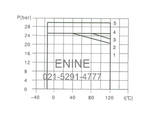
limitation of pressure and temperature
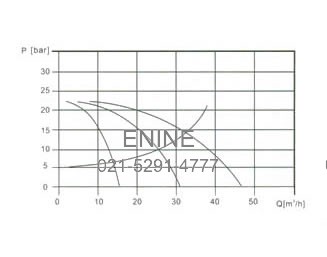
X Performance curve
Following conditions are suitable for the performance curves shown bellow
All the performance curves are based on the measured values of a motor 3
80~415V at a constant speed of 2900 rpm.
Curve tolerance in conformity with ISO9906,appendix A.
Measurement is done with 20
air-free water, kater, kinematics viscosity of 1mm2/s.
The operation of pump shall refer to the performance region indicated by the thickened curve to prevent overheating due to too small flow rate or overload of motor due to too large flow rate.
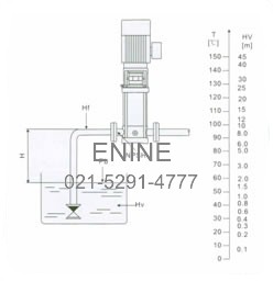
XI NPSH Minimum inlet pressure NPSH
In case that the pressure in pump is lower than the stem pressure used to convey liquid, the capitations will occur. To avoid cavitations, a minimum pressure at the inlet side of the pump shall be guaranteed. The Maximum suction stroke can be calculated with following formula:
H=Pb
0.2-NPSH-Hf-Hv-Hs
Pb=atmosphere pressure [bar]
(can be set as 1bar)
In a closed system, Pb means system pressure[bar]
NPSH=Net positive suction head[m]
(It can be read out from the point of possible max, flow rate shown on NPSH curve)
Hf=Pipeline loss at the [m]
Hv=Steam pressure[m]
Hs=Safety margin=Minimum 0.5m delivery head
If the calculated result H is positive, the pump may run under the max. Suction stroke H.
In case the calculated result H is negative, a delivery head of min. Inlet pressure is necessary
XII Operation in parallel
Connecting several pumps in parallel running will benefit much more than running a single large pump. Applicable to different working states necessary in a variable flow system. Increasing the possibility of water supply when the pump is in failure. Because in case of pump failure, only part of the system flow is effected.
Check and ensure that the pump is not at cavitations state.
Two pump or more can be connected in parallel running if necessary.